RFID Communication Without Power Supply
Author’s note: Starting today, this blog will gradually roll out a series of articles, stepping into the upcoming top academic conference in the field of communication, SIGCOMM 2013, to see what Wireless & Networking researchers around the world are doing. Although these seemingly fancy designs may not work at all in a production environment, they at least point us in some possible directions.
Ambient Backscatter: Wireless Communication Out of Thin Air
Absorbing energy from space and using it as a power source, doesn’t that sound crazy? A research team from the University of Washington has created an RFID card that doesn’t need a power source, can draw energy from TV Towers available in every city to support sensors and microcontrollers, and reflect the energy of the TV Tower’s radio signals, enabling autonomous communication between two RFID cards no more than 50~75 cm apart, with a communication speed of up to 1kbps. To borrow an advertising phrase, it’s “We don’t produce signals, we’re just the porters of TV signals“.
How RFID works
RFID (Radio Frequency Identification) is a technology that can store a small amount of information and read it through radio frequency communication. The meal cards and bus cards we usually swipe are RFID. How do these cards without a power source transmit data to the card reader?
Power supply for chip operation: When the antenna receives the signal from the card reader, it will induce an electromagnetic current, and this weak current is enough to drive the chip to work.
Radio frequency signal carrying information: The antenna will reflect the received radio frequency signal, and amplitude modulation can be performed on the reflected signal. There are two technologies: inductive modulation (for low frequency) and backscatter modulation (for high frequency, with a longer effective distance). In this article, we focus on backscatter.
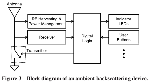
Backscatter is achieved by changing the impedance of the antenna. When electromagnetic waves reach the interface of a medium with different impedance, part of the wave will be reflected, and the proportion of reflected energy is related to the difference in impedance. The chip in the radio frequency card can modulate the information on the reflected wave by changing the impedance of the antenna.
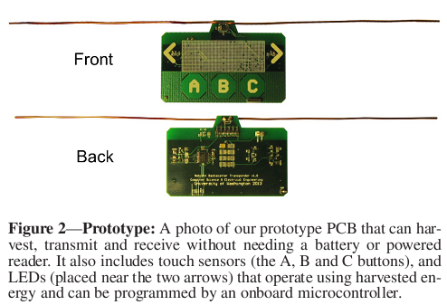
As for how the impedance is adjusted? See the two “braids” in the photo above? A transistor is placed between the two antennas, 0 means the transistor is off, the antenna impedance is matched, and the reflected wave is very weak; 1 means the transistor is on, the two antennas are short-circuited, and there is a certain reflected wave.
In fact, currently commercially available RFID is divided into active, semi-passive, and passive.
- Active RFID has a power source and actively sends its ID at intervals, with an effective distance of more than 100m. Because sending radio frequency signals requires a lot of energy, the battery life is short.
- Passive RFID has no power source, an effective distance of about 1m, low cost, and no theoretical life limit. The meal cards and bus cards we commonly use are passive RFID. It uses the above-mentioned backscatter modulation to transmit information to the card reader. Since there is no continuous power source, it cannot support clocks, sensors, etc.
- Semi-passive RFID combines the advantages of the above two. Semi-passive RFID also has a power source, used to maintain the operation of the chip and (possibly) sensors. The radio frequency signal uses backscatter modulation and does not need to use the energy of the battery, so the battery life can reach 10 years. Since it is not necessary to maintain the operation of the chip with the current induced by electromagnetic induction, the antenna can be optimized for backscatter, so the effective distance can reach about 10m.
Challenges
The TV Tower is a stable signal source and energy source, which sounds good. But when it’s really used, there are two problems:
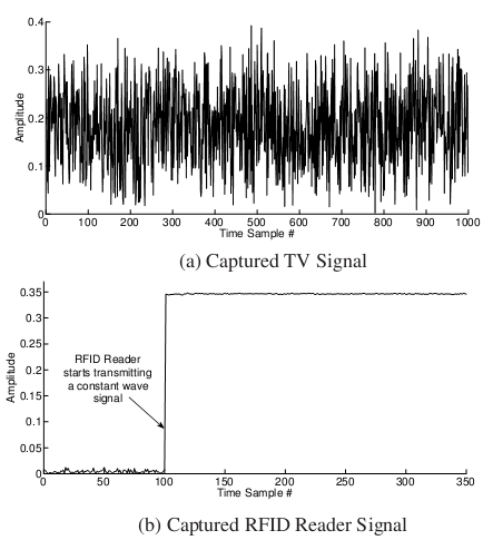
- In traditional backscatter technology, the card reader sends a constant signal, so the card reader can detect minor changes from the weak reflected signal and restore the modulated information. However, the TV signal itself is a noisy signal that has already been modulated with information. (See above figure)
- Compared to the nearby card reader, the TV signal is still too weak. Traditional backscatter technology requires a crystal oscillator, an analog-to-digital converter, digital signal processing logic, etc., and this little energy from the TV signal is not enough to work.
In addition, from the network topology, the card reader is a central controller that can perform FDMA (Frequency Division Multiple Access) to coordinate the communication of each RFID card. Now that there is no center, the radio frequency card must have a set of distributed CSMA (Carrier Sense Multiple Access) protocols. (Of course, if someone uses the most primitive ALOHA, I don’t object)
Challenge #1: Noisy Signal
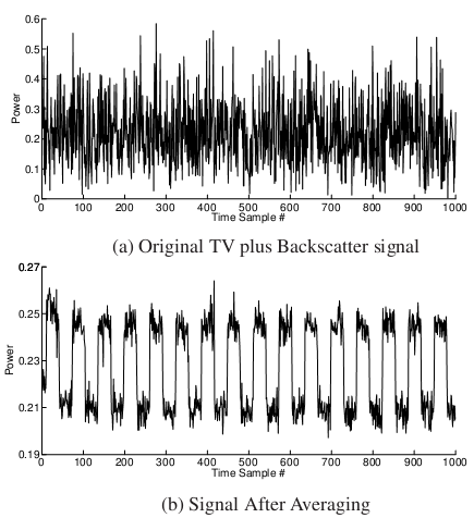
The first problem to solve is that the TV signal is not a constant signal. The paper proposes that if the frequency of backscatter modulation is far lower than the frequency of the background signal (carrier), these two signals can be separated. Intuitively, as long as the average value of several adjacent samples is taken, the background signal will tend to be the same (due to the law of large numbers), and the backscatter modulated signal will stand out.
The bandwidth of the TV signal is generally 6MHz, so backscatter can be distinguished as long as it is modulated in a time domain longer than 6MHz.
Challenge #2: Ultra-low Power
The above method requires an Analog-to-Digital Converter (ADC), but it cannot be implemented on such a low-power passive RF card. The paper designs an equivalent analog circuit.
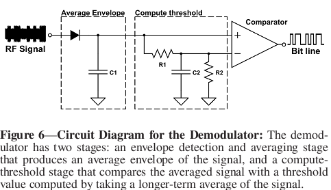
The receiver has two stages:
- Average Envelope Stage: Composed of diodes, C1, R1, and R2. When the input signal voltage is higher than the capacitor voltage, the diode conducts and the capacitor charges; when it is lower than the capacitor voltage, the diode does not conduct, and the resistance slowly consumes the electrical energy released by the capacitor. By adjusting the resistance values of R1 and R2, the above circuit is equivalent to a low-pass filter, filtering out the high-frequency part of the TV signal and leaving the low-frequency backscatter signal.
- Compute-Threshold Stage: Composed of R1, R2, and C2 to form an RC circuit, and then through a comparator. The line above is the output of the first stage, and the line below is the threshold, which is further averaged by C2. In this way, when the signal is higher than the threshold, output 1, and when the signal is lower than the threshold, output 0, thus achieving analog-to-digital conversion.
Network Stack
Since the position of the receiving RF card may change, the reflected signal may either interfere with the TV signal to enhance it, or interfere with the TV signal to weaken it, so the received “0” and “1” may flip at any time. Therefore, the physical layer uses FM0 encoding, using two 0/1 symbols to represent 1bit information, two identical symbols represent 0, and two different symbols represent 1. Flip the symbol before each 2-symbol cycle to ensure the number of 0/1 symbols is the same.
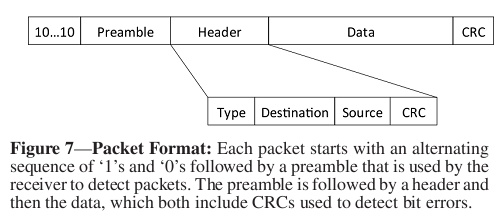
Below is the packet structure of the link layer:
Challenge #3: Carrier Sense
Carrier Sense is an important means to avoid conflicts in non-central wireless networks. A sender, before sending, first listens to the channel, and if it finds that others are sending, it will pause for a while. Without this mechanism, random conflicts would result in very low channel utilization.
In Wifi, Carrier Sense is achieved by comparing the average signal strength and the current signal strength. If the current signal strength exceeds a certain threshold of the average strength, it is considered to be transmitting a packet. However, the receiver in this paper does not have an ADC and cannot detect signal strength.
It is easy to see that for the background signal, because it has passed through the low-pass filter in the first stage, there should be no significant difference in voltage between the two lines before the comparator in the second stage, so the comparator either outputs a long string of 0s or a long string of 1s. Noting that the number of 0/1 symbols in FM0 encoding is equal, as long as the number of received 0/1 symbols is counted, it can be known whether there are other nearby backscatter devices transmitting.
Effective Transmission Distance
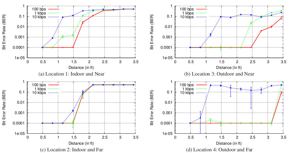
According to whether the RFID card is indoors or outdoors, and whether it is far or near from the TV signal transmission tower, and the transmission bit rate, the proportion of transmission errors is measured: (For specific configuration of the test environment, please see the paper)
As expected, the closer to the TV tower, the better the effect, and the outdoor effect is better than the indoor effect (less reflection and interference), and the slower the transmission, the better. Even in the worst case, 1kbps transmission can be achieved at a distance of 50 cm.
Why would there be a problem with a longer distance? The second stage of the receiver mentioned earlier has a comparator. The voltage difference that the comparator can distinguish is limited. If the signal is too weak, the voltage difference input to the comparator is too small, and the comparator cannot correctly judge which side is high and which side is low.
Application 1: Communication between Smart Cards
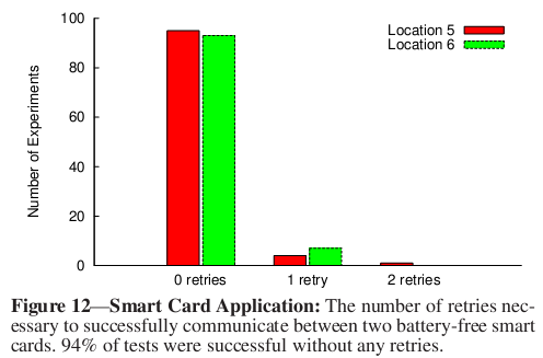
The user touches the “capacitive touch sensor”, and if another card is detected, it will send “Hello world”. When the receiver receives “Hello world”, it will flash the LED light. The smart card uses the MSP430 microcontroller.
The above communication between two smart cards 10cm apart has a 94% chance of success at one time.
Application 2: Checking the placement of goods
Each box of goods is equipped with a radio card, and the ID of the radio card increases in the order of the arrangement of the goods. In this way, the IDs of other radio cards around each radio card should not be far from their own ID. Each radio card broadcasts its own ID every 5 seconds. The nearby radio cards receive and store the received IDs. If a radio card receives two IDs that exceed the threshold from its own ID, it will flash the LED.
The test results given in the paper are that in 50% of the cases, it only takes 20 seconds to detect the wrong placement; even in the worst case, the misaligned radio card starts flashing after 190 seconds.
Comments
This paper describes a wonderful prospect: radio communication without a power source. Unfortunately, due to the weak strength of the TV signal, its effective communication distance is less than 1 meter, which greatly limits its application range. So close, why not have a powered card reader? Low cost, avoiding the trouble of changing batteries, perhaps its advantage.
