Unveiling Google Data Center Networks
Introduction: This is the second article in the “Entering SIGCOMM 2013” series. For the first time, Google has fully disclosed the design and three-year deployment experience of its data center wide area network (WAN), this paper may be rated as Best Paper. Why does Google use Software Defined Networking (SDN)? How to gradually deploy SDN to existing data centers? Through the paper, we can glimpse a corner of the iceberg of Google’s global data center network.
Huge Waste of Bandwidth
As we all know, network traffic always has peaks and troughs, with peak traffic reaching 23 times the average traffic. To ensure bandwidth demand during peak periods, a large amount of bandwidth and expensive high-end routing equipment must be purchased in advance, while the average usage is only 30%40%. This greatly increases the cost of the data center.
Is this waste inevitable? Google observed that the traffic in the data center has different priorities:
- User data copy to remote data centers to ensure data availability and persistence. This data volume is the smallest, most sensitive to delay, and has the highest priority.
- Remote storage access for distributed computing such as MapReduce.
- Large-scale data synchronization to synchronize the status between multiple data centers. This traffic is the largest, insensitive to delay, and has the lowest priority.
Google found that high-priority traffic only accounts for 10%~15% of total traffic. As long as high-priority and low-priority traffic can be distinguished, ensure that high-priority traffic arrives with low latency, and let low-priority traffic squeeze the remaining traffic to full, the wide area network connection (WAN link) of the data center can achieve close to 100% utilization. To achieve this, several aspects need to cooperate:
- Applications need to estimate the required bandwidth in advance. Since the data center is Google’s own, the bandwidth required for various services can be estimated.
- Low-priority applications need to tolerate high latency and packet loss, and adapt the sending speed according to the available bandwidth.
- A central control system is needed to allocate bandwidth. This is the focus of this article.
Why SDN?
When computer networks first emerged, they were all connected to the switch with a wire, and routing rules were manually configured. In situations where the network is not complicated, such as school computer rooms, this is still the case today. However, as soon as a new device is added, you have to go into the computer room and toss about for a long time; if an old device breaks down, there will be a large-scale network paralysis. The maintainers of the wide area network soon couldn’t stand it, so distributed, self-organizing routing protocols such as BGP, ISIS, OSPF, etc. were born.
Why was it designed like this? There are two reasons. First, when the wide area network just emerged in the seventies and eighties, network switching equipment was very unstable, and it would hang up every three days. If a central server allocates resources, then the entire network will be paralyzed every three days. Secondly, the Internet involves multiple parties. Is Stanford willing to listen to MIT’s command, or is MIT willing to listen to Stanford’s command?
Today, in the data center, these two problems no longer exist. First, current network switching equipment and servers are stable enough, and mature distributed consistency protocols such as Paxos can ensure that the “central server” will hardly hang up. Secondly, the scale of the data center is large enough, a large data center can have 5,000 switches and 200,000 servers, which is already comparable to the scale of the entire Internet in the seventies and eighties. The data center is owned by the company, and it can do whatever it wants.
Therefore, Software Defined Networking (SDN) came into being. Represented by OpenFlow, SDN centralizes decentralized autonomous routing control, and routers match packets according to the rules specified by the controller and perform corresponding actions. In this way, the controller can calculate a set of routing rules that are close to the global optimum based on the topology information of the entire network and the demand information from the application. This kind of Centralized Traffic Engineering (TE) has several advantages:
- Use the packet forwarding mechanism of non-shortest path to take into account the priority of the application in resource allocation;
- Dynamically re-allocate bandwidth when connections or switches fail, or when application requirements change, and converge quickly;
- Specify rules at a higher level, for example (I made it up) Gmail’s traffic does not go through China.
Design
Overview
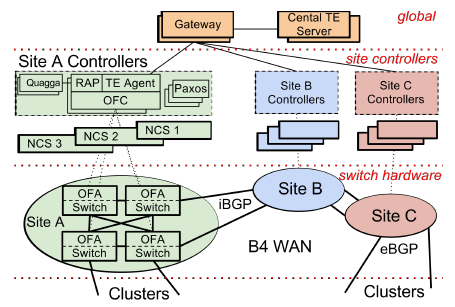
The switch hardware is customized by Google, responsible for forwarding traffic, and does not run complex control software.
The OpenFlow Controller (OFC) maintains network status based on instructions from network control applications and switch events.
The Central TE Server is the central controller of the entire network in logic.
 b4-2
b4-2Above the first dashed line is the Central TE (Traffic Engineering) Server.
Between the first and second dashed lines are the controllers for each data center (Site), known as Network Control Server (NCS). On it runs the OpenFlow Controller (OFC) cluster, which uses the Paxos protocol to elect a master, with the rest being hot standby.
Between the second and third dashed lines are the switches, running the OpenFlow Agent (OFA), which accepts instructions from OFC and writes TE rules into the hardware flow-table. (The details in this diagram will be clear after reading this article)
Switch Design
Google’s custom 128-port switch is made up of 24 generic 16-port 10Gbps switch chips. (In this article, “switch” and “router” are interchangeable. When it is necessary to specify whether it works at the MAC layer or the IP layer, the modifiers layer-2 or layer-3 will be added) The topology is shown in the figure below.

The blue chips are for external wiring, and the green chips act as the backplane. If a packet destined for a blue chip has its target MAC address on the same blue chip, it is “resolved internally”; if not, it is sent to the backplane, and the green chip sends it to the corresponding blue chip.
The switch runs a user-space process OFA (OpenFlow Agent), which connects to a remote OFC (OpenFlow Controller), accepts OpenFlow commands, and forwards appropriate packets and connection states to OFC. For example, BGP protocol packets are forwarded to the OFC, where the BGP protocol stack is run.
Routing
- RIB: Routing Information Base, the network topology, routing rules, etc. needed for routing
- Quagga: An open-source BGP/ISIS protocol implementation used by Google
- RAP: Routing Application Proxy, responsible for the interconnection between OFA and OFC
 b4-4
b4-4
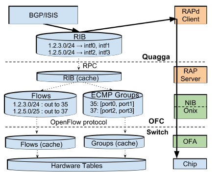
As shown in the figure above, the RIB in the Quagga routing protocol stack stores routing rules, such as which of two ports to choose to send packets to a certain subnet. In a data center network, a packet generally has multiple routes to choose from, which increases redundancy and makes full use of bandwidth. The commonly used protocol is Equal Cost Multiple Path (ECMP), i.e., if there are multiple shortest paths, one is randomly selected.
In OFC, RIB is broken down into Flows and Groups. To understand the necessity of this division, one must first understand how network switching devices work. The core of modern network switching devices is the match-action table. The Match part is the Content Addressable Memory (CAM), all entries can be matched in parallel, and the match result is selected by Mux to choose the highest priority one; Action is the action performed on the packet, such as modifying the packet header, reducing TTL, sending to which port, discarding the packet.
For routing rules, CAM that only supports exact matching is not enough, a more advanced TCAM is needed, and the matching rules support bit-mask, that is, whether the masked bit is 0 or 1 is considered a match. For example, to match 192.168.0.0/24, the first 24 bits are exactly matched, and the last 8 bits are set as masks.
In OFC, Flows correspond to the Match part, which matches to get the Action rule number; Groups correspond to the Action part, using the existing ECMP Hash support in the switch, randomly selecting an exit.
TE Algorithm
Optimization Objectives
The system administrator first decides the bandwidth and priority required for each application between each pair of data centers, forming a series of {Source site, Dest site, Priority, Required bandwidth} tuples (here, the original paper has been modified for ease of understanding). Group these tuples by {Source site, Dest site, Priority}, add up the required bandwidth, and you get a series of Flow Group (FG). Each FG is characterized by a four-tuple {Source site, Dest site, Priority, Bandwidth}.
The goal of TE Optimization is max-min fairness, which is to meet as many needs as possible on the premise of fairness. Since not all needs can be met, a definition must be given to “as many as possible” and “fair”. We believe that customer satisfaction is proportional to the bandwidth provided and inversely proportional to the priority (the higher the priority, the less likely it is to be satisfied); if all the required bandwidth has been provided, satisfaction will no longer increase. Based on this assumption, the concept of fair share is introduced. If two Flow Groups have the same fair share, it is considered that these two customers have the same satisfaction, which is fair.
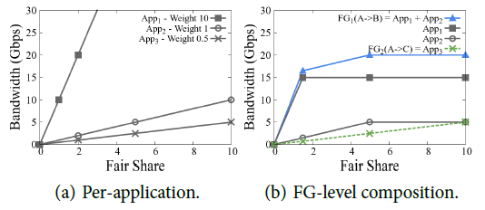
Example: App1 requires 15G bandwidth from A to B, with a priority of 10, as shown in the square in the figure below; App2 requires 5G bandwidth from A to B, with a priority of 1, as shown in the circle in the figure below; App3 requires as much bandwidth from A to C as possible (no upper limit), with a priority of 0.5, as shown by the × in the figure below. We first merge the flows with the same start and end points into a Flow Group, resulting in FG1 = App1 + App2 shown by the blue line and App3 shown by the green line.
The TE Optimization algorithm is divided into the following three steps:
- Tunnel Selection: Select several routes (tunnels) that each FG may take.
- Tunnel Group Generation: Allocate bandwidth to FG.
- Tunnel Group Quantization: Discretize the bandwidth to the granularity that the hardware can implement.
Route Selection
Tunnel Selection: Use the Yen algorithm [2] to select k shortest paths, where k is a constant.
For example, in the network topology below, take k = 3:
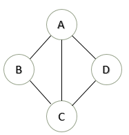
FG[1]: A → B
T[1][1] = A → B
T[1][2] = A → C → B
T[1][3] = A → D → C → B
FG[2]: A → CT[2][1] = A → C
T[2][2] = A → B → C
T[2][3] = A → D → C
Here is the algorithm description for those who love to delve into details:1
2
3
4
5
6
7
8
9
10
11
12
13
14
15
16
17
18
19
20
21
22
23
24# dist: adjacent matrix of node distances
# S: source node
# T: target node
# K: path num
# return: a matrix, each row is a path
def K_shortest_paths(dist, S, T, K):
A = []
A[0] = shortest_path(S, T)
for k in range(1, K):
distcopy = copy(dist)
for i in range(0, len(A[0])):
nodeA = A[k-1][i]
for j in range(0, k-1):
nodeB = A[j][i]
if (nodeA == nodeB):
distcopy[nodeA][nodeB] = inf
candidate[i] = A[0:i] + shortest_path(distcopy, nodeA, T)
A[k] = the path with minimum length for all candidate[i]
return A
# standard algorithm to find shortest path
# return: a list, shortest path from S to T
def shortest_path(dist, S, T):
pass
Traffic Allocation
Tunnel Group Generation: Allocate traffic according to traffic demand and priority. (The paper does not describe the algorithm, I sorted it out myself. Since some terms are awkward to write in Chinese, I used English)
- Initialize each FG with their most preferred tunnels.
- Allocate bandwidth by giving equal fair share to each preferred tunnel.
- Freeze tunnels containing any bottlenecked link.
- If every tunnel is frozen, or every FG is fully satisfied, finish.
- Select the most preferred non-frozen tunnel for each non-satisfied FG, goto 2.
Continue with the example above. (Text explanation see below the picture)
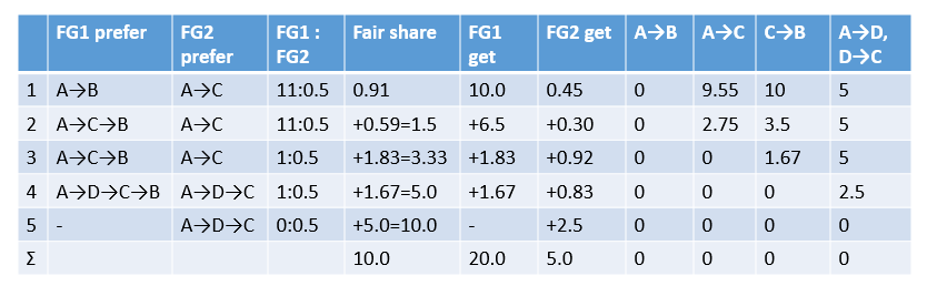
- According to FG1 and FG2’s favorite A→B and A→C, allocate traffic in the ratio of FG1:FG2 = (10+1):0.5. Imagine the traffic gradually increasing until one of A→B and A→C is blocked. The A→B route taken by FG1 is first filled with 10G bandwidth, at this time fair share = 10/(10+1) = 0.91, FG2 gets 0.91*0.5 = 0.45G.
- At this point, A→B can no longer be taken, FG1’s favorite unblocked path is A→C→B, FG2’s favorite path A→C is still unblocked. Based on the fair share = 0.91, first allocate traffic in the ratio of 11:0.5 until fair share = 1.5, at this time FG1 gets (1.5-0.91)*11 = 6.5G, FG2 gets (1.5-0.91)*0.5 = 0.30G.
- Fair share = 1.5 is a turning point on the fair share line graph. After this point, App1 in FG1 is satisfied (allocated 15G), and only App2 is allocated traffic, so the “priority” is reduced to 1. Therefore, the new traffic allocation ratio FG1:FG2 = 1:0.5. The path does not change FG1 = A→C→B, FG2 = A→C, at this time A→C is first blocked, fair share increased by (10G-0.45G-6.5G-0.3G) / (1+0.5) = 1.83, FG1 gets 1.83G, FG2 gets 0.92G.
- After A→C is blocked, FG1’s favorite path is A→D→C→B, FG2’s favorite path is A→D→C. Allocate in the ratio of FG1:FG2 = 1:0.5, when fair share increases to 5.0, there is still 2.5G bandwidth left in A→D and D→C, and C→B is just blocked.
- Fair share = 5 is another turning point on the line graph. At this point, App2 in FG1 is also satisfied, and FG1 no longer needs any bandwidth. The remaining bandwidth is all allocated to FG2. When all paths are blocked, fair share increases by 5.0, which means FG2 gets 2.5G bandwidth.
The allocation result of this example is:
- FG1 is allocated 20G bandwidth, of which 10G goes A→B, 8.33G goes A→C→B, 1.67G goes A→D→C→B.
- FG2 is allocated 5G bandwidth, of which 0.45G goes A→C, 1.22G goes A→C→B, 3.33G goes A→D→C.
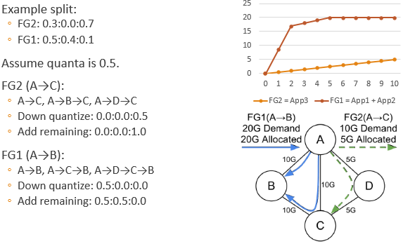
Traffic Discretization
Tunnel Group Quantization: Since the traffic control supported by the hardware cannot be infinitely fine, it is necessary to discretize the traffic calculated in the previous step. Finding the optimal solution is an integer programming problem, which is difficult to solve quickly. Therefore, the paper uses a greedy algorithm.
- Down quantize (round) each split.
- Add a remaining quanta to a non-frozen tunnel that makes the solution max-min fair (with minimum fair share).
- If there are still remaining quantas, goto 2.
Continue the above example:
Will Discretization Reduce Performance?
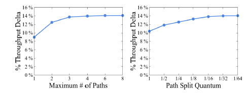
The above figure shows the impact of discretization on performance. The Throughput Delta here is relative to before optimization, the larger the better. It can be seen that when the traffic allocation granularity reaches 1/16, increasing the level of detail does not have much effect.
In Google’s final implementation, the number of tunnels (the k in front) is set to 4, and the allocation granularity is 1/4. As for why it is set this way, you ask me, I ask who.
TE Implementation
Tunneling
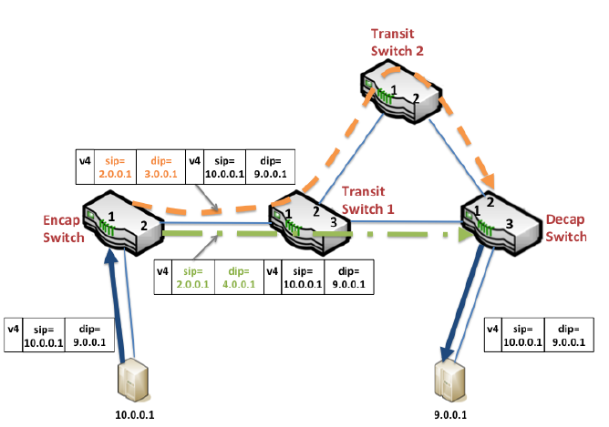
- The Encap Switch is the border router connecting the terminal machines. They encapsulate the IP packet, with a dedicated source ip and destination ip for routing.
- The Transit Switch is the intermediate transmission router. They only accept IP packets encapsulated by the Encap Switch and route them between data centers.
- The Decap Switch is the border router connecting the terminal machines, which is actually the same batch of machines as the Encap Switch. They peel off a layer of the encapsulated IP packet and deliver it to the terminal machine.
TE as Overlay
The “one-step” approach of SDN is to design a unified, centralized service that includes routing and Traffic Engineering. But the development process of such a protocol would be long. Moreover, if there is a problem, everyone will not be able to access Google.
On this issue, Google has once again carried forward the agile development thinking of “small steps and quick walks”, running the TE and traditional routing systems in parallel, with TE having a higher priority than traditional routing. This way, SDN can be gradually deployed to various data centers, allowing more and more traffic to switch from traditional routing to the TE system. At the same time, if there is a problem with the TE system, you can turn off TE at any time and return to traditional routing.
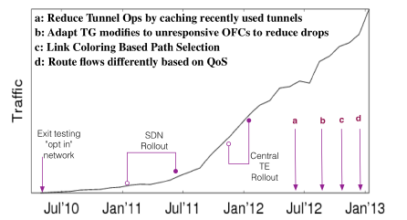
The above figure is the traffic change curve carried by Google SDN.
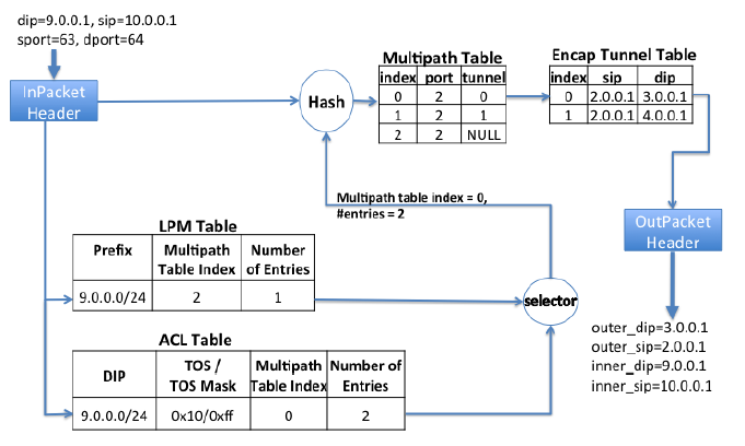
Each switch has two routing tables. The LPM (Longest Prefix Match) Table is maintained by the traditional routing protocol based on the shortest path (BGP/ISIS). The ACL Table is the routing table used by TE, which has a higher priority than LPM, that is, when both LPM and ACL match an entry, ACL has the final say.
The example in the above figure is the Encap Switch. The match result is a Multipath Table Index and optional items, that is, a rule is selected from so many rules starting from the Index according to the Hash value. This rule specifies the exit (port) and path (tunnel), and then the source IP and dest IP to be encapsulated in the IP packet header are found from the path table (Encap Tunnel Table). For the Transit Switch, no path table is needed.
Operation Dependencies
A TE change may involve the insertion/deletion of rules on multiple switches, and these operations cannot be performed in any order, otherwise packet loss may occur. Therefore, there are two rules:
- Before modifying the Tunnel Group and Flow Group, first establish tunnels in all affected data centers
- Before all entries referencing a tunnel are deleted, this tunnel cannot be deleted
In order to ensure dependencies in the case of network delay and packet reordering, the central TE server assigns increasing sequence numbers to the ordered operations in each transaction (session). The OpenFlow Controller maintains the current maximum session sequence number and rejects any session sequence number smaller than it. If the TE server is rejected by the OFC, it will retry this operation after a timeout.
Deployment Effect
Statistics
13 topology changes per minute
Excluding updates caused by maintenance, 0.2 topology changes per minute
Edge addition/deletion events in the topology, 7 times a day (The TE algorithm runs on the view after topology aggregation. There may be hundreds of links between two data centers, which are aggregated into a single link with huge capacity.)
The experience in this area is:Topology aggregation significantly reduces path bumps and system load
Even with topology aggregation, edge deletions occur several times a day
WAN link is very sensitive to port bumps (repeated changes), and centralized dynamic management is more effective
Error Recovery
In data centers, equipment and line damage are common, so the scope of error impact and recovery speed are important.

As can be seen from the above table, a single line damage will only interrupt the connection for 4 milliseconds, because the two affected switches will immediately update the ECMP table; a damaged Encap Switch will cause all surrounding switches to update the ECMP table, which takes a bit longer than a single line damage.
However, it’s not fun when the Transit Switch near the Encap Switch goes down, because there is an encapsulation path table (Encap Tunnel Table) in the Encap Switch. This table is centrally maintained. When a fault occurs, the neighboring Encap Switch needs to report to the OFC, the OFC reports to the global center’s TE Server (high latency), and the TE Server, according to the order of operation dependency, notifies the affected Encap Switches one by one to modify the path. Since this operation is slow, it takes 100ms, and the entire recovery transaction takes 3300ms to complete.
Failures of OFC and TE Server have no impact, firstly because they use the Paxos distributed consistency protocol, and secondly, even if they all go down, they just can’t modify the network topology structure, and won’t affect the existing network communication. Due to the previously mentioned TE as Overlay, when TE is turned off, the entire network will return to the traditional routing protocol based on the shortest path, so it will not cause network interruption.
Optimization Effect
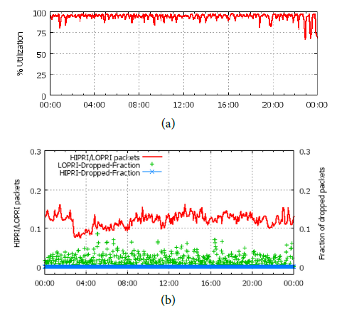
(a) is the average bandwidth usage rate, which can reach an average of 95%.
(b) is the packet loss rate, where high-priority packets (red line) accounting for 10%~15% of the proportion almost have no packet loss (blue), while low-priority packets have a lot of packet loss (green). If low-priority applications use the usual TCP protocol, it is difficult to work efficiently under such a high packet loss rate. Therefore, the transport layer protocol also needs to be specially designed, but the paper does not reveal this.
An Accident
Google’s SDN system once had a major accident. The process was as follows:
- A newly added switch was accidentally configured with the same ID as the original switch.
- Two switches with the same ID sent ISIS Link State Packets separately. The other switches that received them felt strange. How could these two topologies be completely different? The two switches with the same ID both insisted that their observations were correct, causing flooding in the network.
- The TE control signaling had to be sent from OFC to OFA, but it was blocked by the network, resulting in a long waiting queue of up to 400MB.
- The ISIS Hello message (heartbeat packet) was also blocked due to the long queue, and the switches all thought that the surrounding switches had gone down. However, TE traffic was still running normally because its priority was higher than traditional routing.
- At this time, due to network congestion, the TE Server could not establish new tunnels. To make matters worse, the TE dependency mechanism requires that operations with smaller sequence numbers succeed before the next operation can be performed (see above), so it is even more impossible to establish new tunnels. Therefore, any network topology changes or equipment failures will cause the affected network to still use tunnels that are no longer usable. There are statistics above that topology changes occur every minute, so this problem is very serious.
- The system operators did not know the root cause of the problem at the time, so they restarted the OFC. Unfortunately, this restart triggered a bug in the OFC that had not been discovered, and it could not self-start when the low-priority traffic was large.
The paper says that there are several experiences/lessons from this failure:
- The scalability and reliability of communication between OFC and OFA are very important.
- The hardware programming operations of OFA should be asynchronous and parallel.
- More system monitoring measures should be added to detect early warnings of failures.
- When the TE connection is interrupted, it will not modify the existing routing table. This is a fail-safe measure to ensure that the tunnels already established in this failure have not been damaged.
- The TE Server needs to handle the situation where the OFC is unresponsive. If some OFCs go down, it is better to let some of them start running first, rather than prohibiting all new tunnel operations.
Conclusion
Compared with other data center papers in SIGCOMM 2013, this paper is the only one that has been widely tested in practice. Although the algorithms and ideas in the paper are very simple, they fully reflect the tradeoffs that have to be made in the engineering field. It has to be said that Google is still the leader in the field of data centers. It is silent but startling when it makes a sound :)
Some future research directions:
- Overhead of hardware programming. The order of OpenFlow rules is very important, inserting a rule may cause all subsequent rules to move, so it is slow to operate. This is the main bottleneck for reliability.
- Communication bottleneck between OFC and OFA. The scalability and reliability of communication between OFC and OFA are insufficient. OpenFlow should ideally provide two communication ports, supporting high-priority operations and data transmission requiring large bandwidth respectively.
I also made a PPT (unofficial), which is similar to the content of this article: B4-Google-simcomm13
References:
- B4: Experience with a Globally-Deployed Software Defined WAN. to appear in SIGCOMM’13
- Yen, J. Y. Finding the K Shortest Loopless Paths in a Network. Management Science 17 (1971), 712-716.
- Koponen, T. Onix: a Distributed Control Platform for Large-scale Production Networks. In Proc. OSDI 2010, pp. 1-6.